Aircraft Cables are strands, cords, and wire rope made of special-strength wire. They were originally designed for use in the aircraft industry and for military applications requiring a higher level of inspection and traceability.
However, due to its size and functionality Aircraft Cable has a wide range of commercial applications as well. Aircraft Cable is identified by the number of groups of strands and the number of strands in each group for a piece of cable.
For example, the notation 7x19 means the rope has seven (7) groups of strands and there are nineteen (19) strands in each group.
Aircraft Cable Types:
· Galvanized
· Stainless Steel
· Mil-Spec Grade (MIL-W-83420)
· Commercial Grade (SD117)
· Vinyl, Nylon, and Teflon Coated
Aircraft Cable Constructions:
· 1 X 7 Non-Flexible
· 1 X 19 Non-Flexible
· 7 X 7 Moderately Flexible
· 7 X 19 Very Flexible
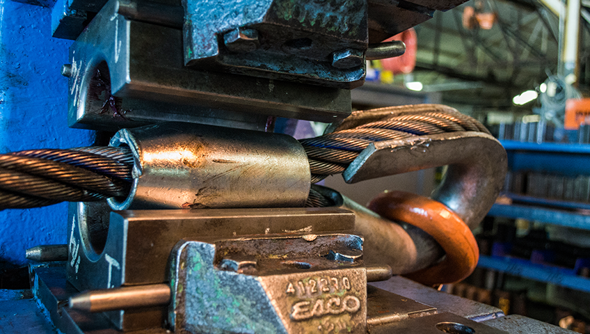
Wire Rope is constructed by taking multiple groups of multi-wire strand and twisting them around a central core.
Wire rope is specified by the number of groups of strands, the number of strands in each group, and a description of the type of construction.
For example, the notation 6x7 FC means that the wire rope has 6 groups of strands and there are 7 strands in each group all surrounding a fiber core.
Wire Rope Specifications
TYPES OF CORES
An important point to consider is the selection of the proper type of core needed in the rope. Wire Ropes are made with either fiber core or steel wire core.
1) Fiber Core (FC)
This center is made of either natural fibers or polypropylene and offers greater elasticity than the independent Wire Rope Core.
2) Independent Wire Rope Core (IWRC)
This center is usually composed of a separate 7x7 wire rope designated as IWRC. The steel core increases the strength by 7% and the weight by 10%. These steel cores provide more substantial support than fiber cores to the outer strands during the rope's operating life. Steel centers resist crushing, are more resistant to heat and increase the strength of the rope.
DESIGN FACTOR
The Design Factor being both the ratio between the minimum Breaking load of the rope and the rated capacity (RC) tells at what percentage of its ultimate strength a wire rope is operating. The Design Factor takes into consideration both normal rope wear and potential stresses in various applications. The best practice in determining an adequate design factor is to analyze the specific conditions involved inn each individual installation. The following example shows how to determine the Design Factor: If a rope is working under a max. operating load of 10,000 lbs. and is having an ultimate strength of 50,000 lbs., the factor is 5 which means it is operating at 20% of its ultimate strength.
FLEET ANGLE
The fleet angle is the angle formed between the rope running to or from the extreme left or right of the drum and a line drawn from